

[NEFSS Technical Series #04]Essential Checklists for PSV Selection: Face-to-Face Dimensions, Bonnet/Lever Types, and Test Gags
- nick so
- Jan 20
- 6 min read

Hello, this is Nick from NEFSS.
In our last session, we took an in-depth look at the operating principles and types of pressure safety valves (Full Bore vs. Lift Type). Now that we understand the mechanism of how a PSV actuates, it is time to focus on the 'practical specifications' encountered during actual product ordering and field installation.
Simply matching the set pressure and size does not mean all preparations are complete. Today, we will take a detailed look at the selection criteria for accessories based on fluid characteristics, as well as Face-to-Face (F-to-F) dimensions—the area where issues most frequently arise at actual installation sites.
What is the Face-to-Face Dimension?
The Face-to-Face (F-to-F) dimension refers to the distance between the two flange faces of a valve.

Unlike standard valves, a Pressure Safety Valve (PSV) has an 'Angle' configuration where the inlet and outlet are oriented at a 90-degree angle.
Therefore, instead of measuring a single overall length, you must verify both the height from the center to the inlet (A) and the distance from the center to the outlet (B).
(Please note that 'A' and 'B' are used here as arbitrary labels; nomenclature may vary depending on each manufacturer's drawing—for example, using terms like L, H1, etc.)
Why are Face-to-Face (F-to-F) dimensions so important?
When requesting a quote, customers often demand that the dimensions match a competitor's product or insist on a specific F-to-F measurement because their existing piping cannot be modified.
Why do customers place such high importance on these dimensions?
Quite simply, if the F-to-F dimension does not align with the existing piping, it is impossible to bolt the valve into place.
Let’s take a closer look at the details through the illustration below.

If the Face-to-Face (F-to-F) dimensions of the Pressure Safety Valve (PSV) do not match the existing piping specifications, proper installation becomes impossible, as shown in the photo on the left.
When installation is delayed on-site due to such dimensional discrepancies, it not only causes significant disruptions to the overall construction schedule but can also lead to substantial and unexpected economic losses.
Therefore, it is absolutely critical to verify and align the exact F-to-F dimensions starting from the technical review stage.

Only when the Face-to-Face (F-to-F) dimensions of the Pressure Safety Valve (PSV) exactly match the existing piping specifications can a proper installation be achieved, as shown in the photo on the left.

"Generally, when the fluid is Steam and it is discharged directly into the atmosphere without any connected outlet piping—as shown in the photo on the left—the Face-to-Face (F-to-F) dimensions do not necessarily require strict consideration.
Comparison of Face-to-Face Dimensions: API 526 vs. Maker Standard
API 526 is the code governing "Flanged Steel Pressure-Relief Valves," defining orifice areas, valve sizes, pressure/temperature limits by rating, and Face-to-Face (F-to-F) dimensions. In this post, we will focus on F-to-F dimensions, which are critically important in field practice.
Let’s compare the differences between the API 526 standard and a manufacturer's own standard (Maker Standard) under the same conditions through the example below.
[Comparison Example Conditions]
Size: 1" X 2"
Rating: 150# RF X 150# RF
3-1. Face-to-Face Dimensions based on API 526 Standard
The image below is an excerpt from the "D Orifice" section of the API 526 code.
Looking at the highlighted 'Center-to-Face Dimension' column, you can see the dimensions for both the inlet and outlet specified in inches.
Center-to-Inlet (A): This refers to the distance from the center of the valve to the end of the inlet, corresponding to 'A' on the drawing.
Center-to-Outlet (B): This refers to the distance from the center of the valve to the end of the outlet, corresponding to 'B' on the drawing.

The detailed dimensions for the model specified in the API 526 standard are as follows:
CENTER TO INLET: Corresponds to 'A' on the drawing and is 4⅛ inches
(approx. 105 mm).
CENTER TO OUTLET: Corresponds to 'B' on the drawing and is 4½ inches (approx. 114 mm).
3-2. Face-to-Face Dimensions based on Maker Standard
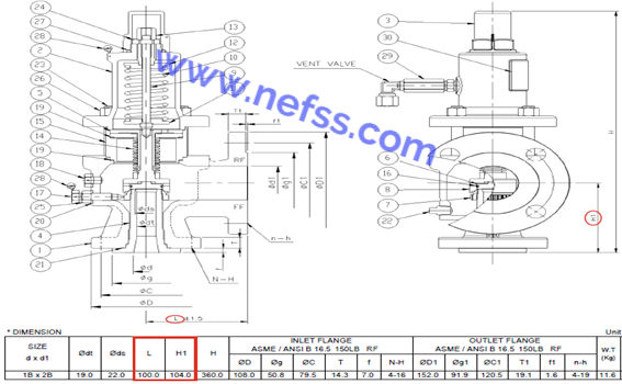
Referring to the drawing on the left:
'H1' on the drawing corresponds to 'A'.
'L' on the drawing corresponds to 'B'.
The Face-to-Face dimensions for this model are as follows:
A (H1) _ CENTER TO INLET: 104 mm
B (L) _ CENTER TO OUTLET: 100 mm
As shown above, there is a clear difference between the API 526 standard and the Maker Standard in terms of Face-to-Face (F-to-F) dimensions.
If the customer's Specification Requirement explicitly states "Compliance with API 526 Standard," the 'A' and 'B' dimensions will be identical regardless of which manufacturer supplies the valve.
However, there is a crucial point to keep in mind. Just as the overall length and width differ between a Toyota Highlander and a Ford Explorer—even though they both belong to the same "Large SUV" category—F-to-F dimensions can vary by manufacturer even for valves with the same technical specifications, unless a specific standard is required.
Therefore, during piping design or field maintenance, please ensure you carefully verify in advance whether the product's dimensions follow an international standard or the manufacturer’s unique specifications.
"Four Types of Safety Valve Configurations Based on Bonnet and Lever Design

Plain Levers are primarily used for Air or Steam services where small amounts of fluid leakage to the atmosphere are permissible. Since high temperatures can affect the spring inside the bonnet, an Open Bonnet design is typically applied for Steam services, which involve higher temperatures compared to Air.

For liquid services or toxic gases where fluid leakage must be strictly prevented, a lever is typically not installed. However, if a customer specifically requests one, a Packed Lever is provided. Unlike a Plain Lever, a Packed Lever ensures that no fluid escapes to the outside, even when the lever is attached.
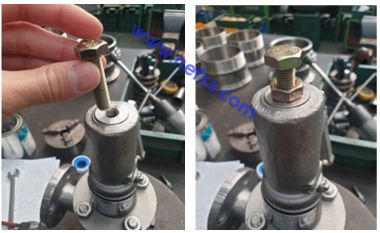
For your reference, the Lever attached to a safety valve is used to manually force the valve to open (Popping) when necessary. As shown in the photo above, there are two main types depending on the characteristics of the fluid:
PLAIN LEVER: Primarily applied to Air or Steam systems where a small amount of fluid leakage to the outside is acceptable.
PACKED LEVER: Applied to Liquids or Toxic Gases that could be hazardous if leaked; it features a sealed structure to prevent any release to the atmosphere.
A critical point to note when operating the lever is that manual popping should only be performed when the inlet pressure is at approximately 70–80% of the Set Pressure.
Occasionally, operators attempt to force the lever up when there is no inlet pressure at all, which can cause component damage. To ensure safe equipment operation,
please refrain from such excessive force.
TEST GAG
A Test Gag is a tool used to prevent a safety valve from activating during pressure tests or inspections of the piping system where the valve is installed.
To help you understand, let’s look at an example.
Suppose a safety valve with a Set Pressure of 10 bar is installed on a pipeline, and you need to increase the internal pressure to 15 bar for a piping test. In this situation, if the safety valve operates normally, the pressure will escape, making it impossible to conduct the test properly. In such cases, a Test Gag is mounted on top of the cap to hold the valve closed, preventing it from activating even when the pressure exceeds the Set Pressure.
However, there is a critical caution: After the test or inspection is complete, the Test Gag must be removed so that the safety valve can return to its normal operational state. Failure to do so will prevent the safety valve from functioning during an emergency, which could lead to a catastrophic accident. Extreme vigilance is required.

🛠️Technical Consultation & Request for Quotation
If you are having difficulty selecting the right safety valve or need a fast and reliable quote, please feel free to contact NEFSS at any time!
[Coming Up Next] In this post, we have taken a detailed look at the importance of Face-to-Face dimensions—which are often overlooked in the field—as well as the various types of Bonnets and Levers, and the proper use of Test Gags.
In our next session, [Part 5: Master Setting Methods and Technical Terminology], we will cover the pressure adjustment methods (Set vs. Closing Pressure) that every practitioner must know. We will also demystify essential technical terms such as Stellited and CDTP, making them easier to understand and apply in practice.
At NEFSS, we go beyond simple material supply to become a partner that cares about your site's safety.
Thank you. Best regards, Nick, NEFSS
![[NEFSS Tech Series #05] PSV Core Settings and Terminology: From Set Pressure to CDTP](https://static.wixstatic.com/media/c2959f_d5105eb98aa0464f880e6b1f4a61a964~mv2.jpg/v1/fill/w_510,h_160,al_c,q_80,enc_avif,quality_auto/c2959f_d5105eb98aa0464f880e6b1f4a61a964~mv2.jpg)


Comments